Phase

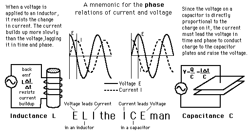
When capacitors or inductors are involved in an AC circuit, the current and voltage do not peak at the same time. The fraction of a period difference between the peaks expressed in degrees is said to be the phase difference. The phase difference is <= 90 degrees. It is customary to use the angle by which the voltage leads the current. This leads to a positive phase for inductive circuits since current lags the voltage in an inductive circuit. The phase is negative for a capacitive circuit since the current leads the voltage. The useful mnemonic ELI the ICE man helps to remember the sign of the phase. The phase relation is often depicted graphically in a phasor diagram.

Index

AC circuit concepts
  HyperPhysics***** Electricity and Magnetism Go Back


Phasor Diagrams

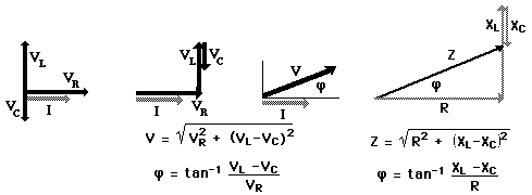
It is sometimes helpful to treat the phase as if it defined a vector in a plane. The usual reference for zero phase is taken to be the positive x-axis and is associated with the resistor since voltage and current are in phase. The length of the phasor is proportional to the magnitude of the quantity represented, and its angle represents its phase relative to that of the current through the resistor. The phasor diagram for the RLC series circuit shows the main features.

AC behavior of inductorAC behavior of capacitor
Index

AC circuit concepts
  HyperPhysics***** Electricity and Magnetism Go Back


ELI the ICE man

PhasePhasor diagrams
Index

AC circuit concepts
  HyperPhysics***** Electricity and Magnetism Go Back