Binary Counting

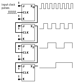
A binary counter can be constructed from J-K flip-flops by taking the output of one cell to the clock input of the next. The J and K inputs of each flip-flop are set to 1 to produce a toggle at each cycle of the clock input. For each two toggles of the first cell, a toggle is produced in the second cell, and so on down to the fourth cell. This produces a binary number equal to the number of cycles of the input clock signal. This device is sometimes called a "ripple through" counter. The same device is useful as a frequency divider.

Decade Counter
Flip-Flops
Index

Electronics concepts

Digital circuits

Data Transfer

J-K Flip-Flop Applications

Reference
Tocci
Digital Systems, Sec 5-19
 
HyperPhysics*****Electricity and magnetismR Nave
Go Back


BCD or Decade Counter

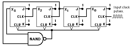
A BCD counter or decade counter can be constructed from a staight binary counter by terminating the "ripple-through" counting when the count reaches decimal 9 (binary 1001). Since the next toggle would set the two most significant bits, a NAND gate tied from those two outputs to the asynchronous clear line will start the count over after 9.

Index

Electronics concepts

Digital circuits

Data Transfer

J-K Flip-Flop Applications

Reference
Tocci
Digital Systems, Sec 7-2
 
HyperPhysics*****Electricity and magnetismR Nave
Go Back


Frequency Division

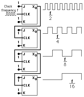
A frequency divider can be constructed from J-K flip-flops by taking the output of one cell to the clock input of the next. The J and K inputs of each flip-flop are set to 1 to produce a toggle at each cycle of the clock input. For each two toggles of the first cell, a toggle is produced in the second cell, so its output is at half the frequency of the first. The output of the fourth cell is 1/16 the clock frequency. The same device is useful as a binary counter.

Flip-Flops
Index

Electronics concepts

Digital circuits

Data Transfer

J-K Flip-Flop Applications

Reference
Tocci
Digital Systems, Sec 5-19
 
HyperPhysics*****Electricity and magnetismR Nave
Go Back


Frequency Counter

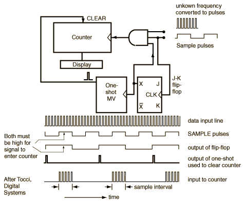
A frequency counter can be made from a binary counter and a decoder/display unit. In the schematic below an AND gate is used as an input device. The unknown frequency is applied to one input of the AND and sample pulses of precise time interval are applied to the other. When the sample pulse is high, the input signal is transferred to the counter. The number of counts divided by the sample time interval gives the frequency. In the design shown, there is another practical element: after the count is done, there must be time to view the result on the display, so a third input to the AND gate is taken from a J-K flip-flop. The input reaches the counter only when both the sample pulse and the J-K flip-flop are high (counts are collected on alternate sample pulses). This provides an interval when the frequency is displayed. On each positive-going edge of the J-K, a one-shot multivibrator is triggered to send a pulse for resetting the counter.

Flip-Flops
Index

Electronics concepts

Digital circuits

Sequential Operations

J-K Flip-Flop Applications

Reference
Tocci
Digital Systems, Sec 7-16
 
HyperPhysics*****Electricity and magnetismR Nave
Go Back